
On this page I will detail the installation of the Kubota RTV900 hydraulic dump bed option
Here is picture of all the parts included in the kit. Hydraulic reservoir, control lever, mounting hardware, control cable, hydraulic pump, hydraulic cylinder, and hydraulic control valve.

The first step is to remove the four bolts on the cover that seals the drive gear port/window located on the top of the hydrostatic transmission.

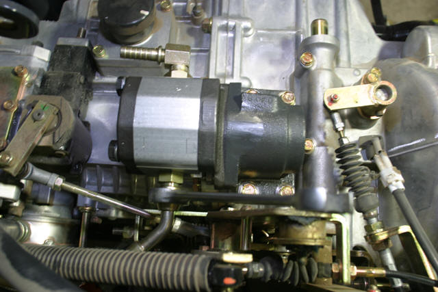
Here is a close-up of the drive gear that turns the hydraulic pump.

This is the hydraulic pump that bolts onto the transmission. Included are two index pins that need to be installed into the transmission prior to installing the pump.
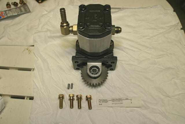
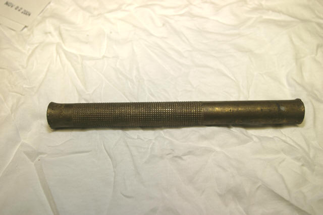
It is important to clean out any hydraulic fluid or debris from the index pin holes on the top of the transmission. The fit of the pins in the transmission are very tight and any hydro fluid or debris will prevent you from installing them to the proper depth. You will also need something softer that the pins to drive them such as a brass drift.
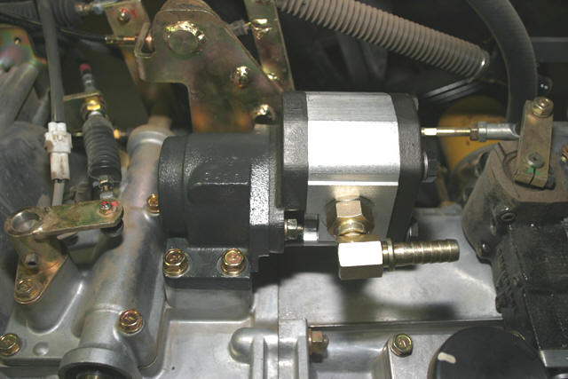
I apllied thin bead of Permatex Ultra Grey sealant along the groove machined into the transmission gear port and installed the pump. Tightening the bolts in a criss-cross pattern allows the pump to seat on the index pins correctly.
Next step is to install the hydraulic control valve. It already comes with the high-pressure hose attached. None the less, check it for tightness.
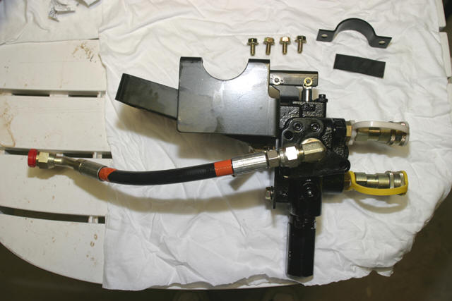
The hydraulic control valve mounts to the cross member tube via a formed steel strap and lower support bracket.
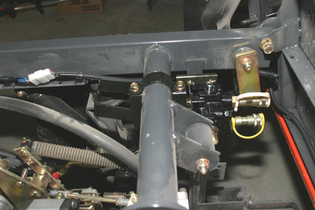
Next, connect and tighten the high pressure hose to the hydraulic pump outlet.
The hydraulic reservoir brackets are next.
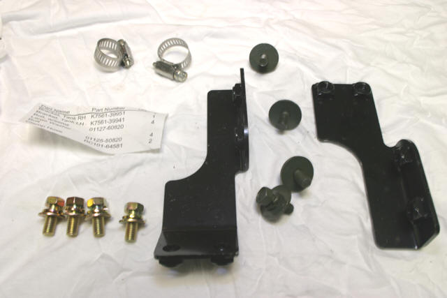
The two bracket mount to the engine support frame. Only install the bolts hand tight as the alignment may be off in respect to the bolt holes on the reservoir tank.
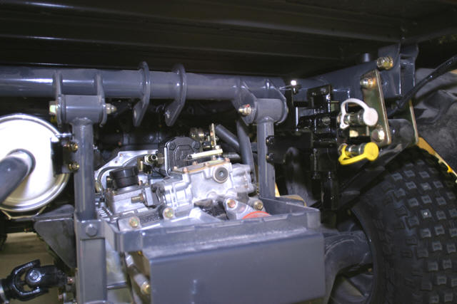
Install and bolt the reservoir to the brackets with the supplied bolts. Tighten the bracket bolts, but be careful not to over-torque the bolts that attach the reservoir to the brackets as this could crack the plastic.
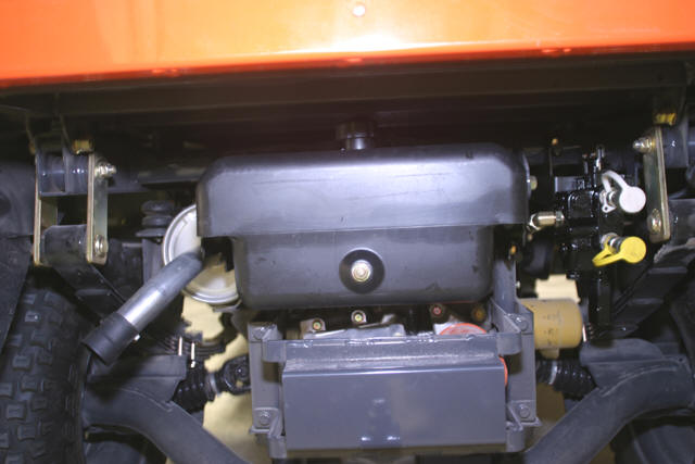
Connect the suction and return lines to the pump and the control valve respectively.
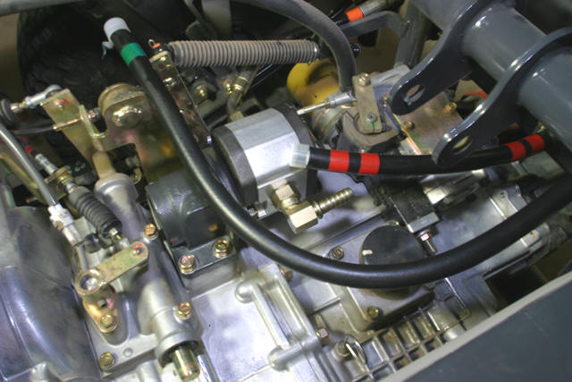
The suction and return lines are low pressure and are held in place with the supplied hose clamps.
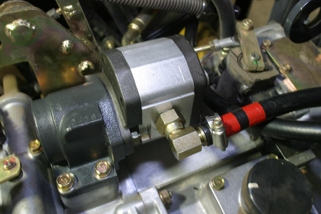
Next, remove the drivers side trim panel in order to install the control lever and control cable assembly.
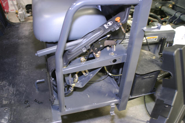
Install the cable bracket and control lever pivot.
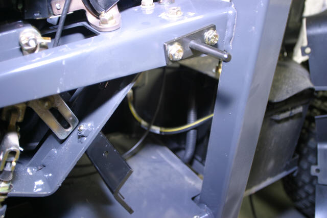
Install the control lever and cable. Route the cable under the seat and along the right side frame rail to the control valve.
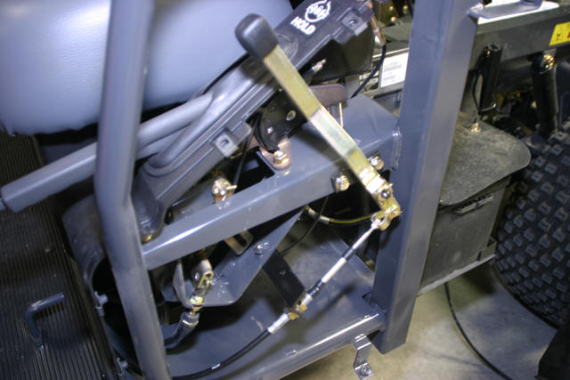
Attach the opposite end of the control cable to the control valve bracket. Adjust the cable adjustment bolts so the control lever is centered.
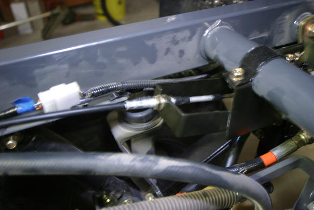
Reinstall the trim and install the safety lockout.
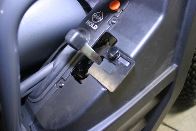
Next is the installation of the bed lift cylinder.
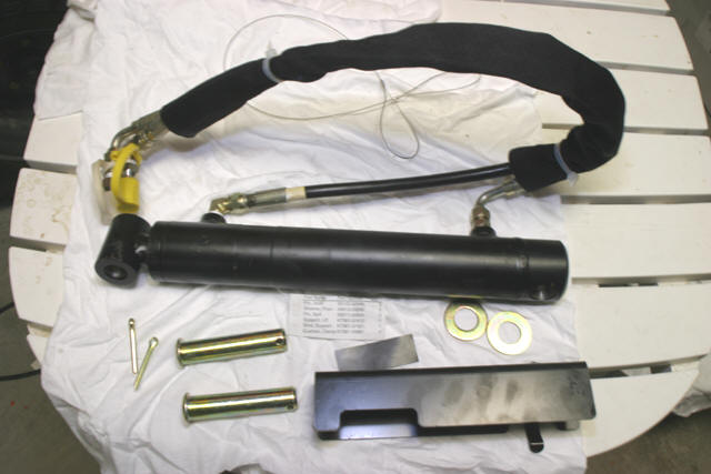
Attach the lower end of the cylinder to the frame cross member and route the hoses under the hydraulic reservoir and connect to the control valve quick-connectors.
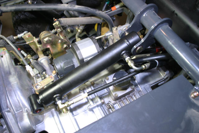
Fill the hydraulic reservoir with hydraulic fluid and start the RTV. Extend the cylinder using the control lever then turn off the RTV and install the upper cylinder pin.

The last step is to remove the dump bed clamps.
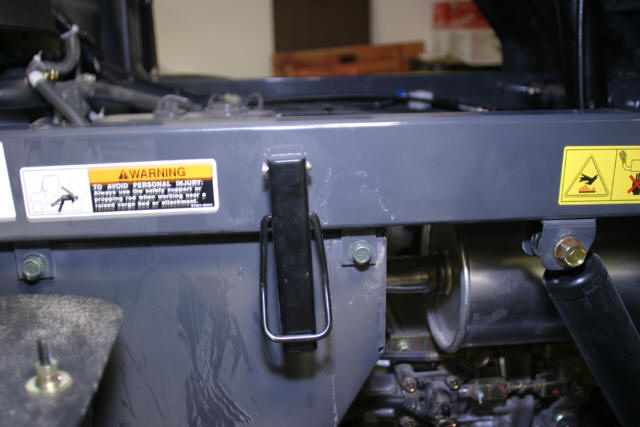
You don't want to leave these on as you risk bending the box if you extend the cylinder with the bed locked down.
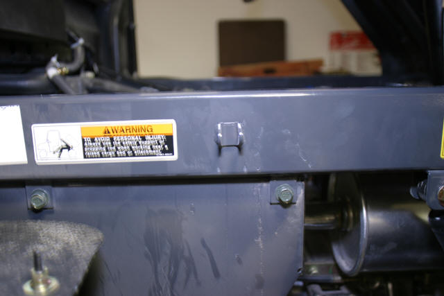
That's all folks. Go have fun!... err... work, I mean.
-Eddie Cornejo